Modelling a thrust vectoring jet engine in Blender
1. Introduction
I've seen a lot of good (blender) animations, made by skilled people, which involved jet engines. Unfortunately, most of them didn't look too impressive as far as the jet engines are concerned. Hoping I could do a better job myself (and whether I did, I'll leave up to you...), I decided to investigate the matter and experiment until I had a convincing result. For the maximum effect, I decided to make a thrust vectoring jet engine, as opposed to a fixed jet, suitable for animation. This involved a complex set of constraints and particle physics, but it worked out very well.
To share my ideas, I wrote this tutorial. It's not for beginners (I will not explain dupliverts or the modelling itself, for example), because it is my intention to aid experienced artists in improving their already advanced work with it. The source .blend files describing each step are available, because they are more informative than screenshots alone.
I used Blender version 2.45. Since then, many new versions have been released, and I noticed several problems with the particle system. I haven't used Blender for a long time, so unfortunately, I'm unable to fix this. The particles not rendering is (or, used to be) explained in the Blender 2.46 release log, but there are also some other issues with the physics and the material.
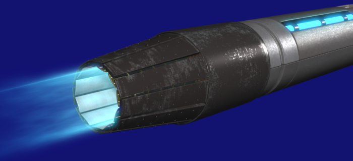
Here's the result:
2. Prelude to modelling
First, it's a good idea to look up how exactly a (thrust vectoring) jet engine works. Only when you're past the stage of a vague familiarity of what it looks like, will you be able to model it.
Then, you have make a plan. To be precise, you have to decide how many blades the thrust nozzle is going to consist of. A good way of doing this, is making a mock-up of a nozzle blade and duplivert it on a circle. I chose 11 (actually, it kind of worked out to be 11 in my case; I didn't choose anything...), so I'll use that. The reason to plan how much blades you will need, is because if you were to model one blade at random, it's likely that it won't fit an exact number of times in one circle, leaving one or multiple gaps between the blades. It is important to keep the object center at the base of the blade, because that will be the pivot point. Dupliverting will not go very well either, if you place the object center somewhere else.
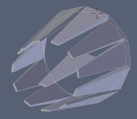
Mock-up nozzle blade dupliverted.
3. Getting down and dirty
Now you can start modelling the nozzle blades. I used three layers of blades. In real life their functions would be: the outer blades for protection, the mid blades to which the hydraulics attach and the inner blades for the actual thrust vectoring.
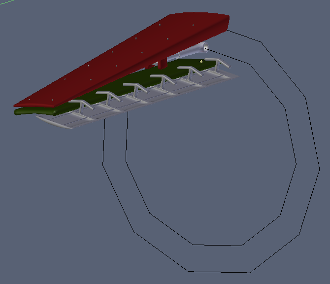
One set of blades modelled.
As you can see, the circle I used for dupliverting is still there, because I use it as a guide, which is needed later on when duplicating the blades. You can't use dupliverts to duplicate them, because the blades need to move individually and because in the end, you will make single instances of each blade, to let them each have a unique material, otherwise you will get ugly texture repetition.
The next step is to add some empties for controling the movement contraints. You will need one control empty at the center of the thrust nozzle (called "thrust target" in the .blend files) and six empties for each set of blades:
- Outer blade target
- Mid blade target
- Inner blade target
- Outer blade base
- Inner blade base
- Inner blade target assist
The target empties should be placed at the same height (z-coordinate) as the object center for the blade in question. The base empties (two per blade-set) should be parented to the thrust target.
The reason for the base and assist empties, is because I want to control how wide the nozzle opens by changing the scale of the thrust target empty. If these three additional empties weren't there, you'd have to parent all of the target empties to the thrust target empty, which has the problem that they will change scale along with the thrust target empty. Instead, the base empties are parented to the thrust target empty, and the targets have a copy location contstraint, copying the location of the bases.
If it seems somewhat complicated, I'd advice you to fiddle around with the .blend file, which should make it more clear.
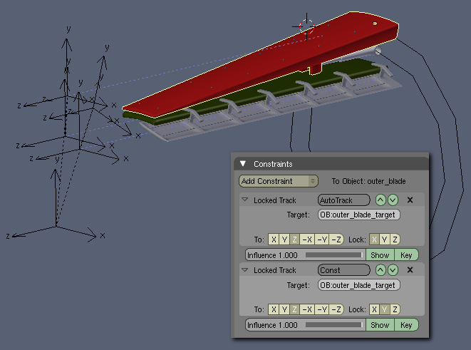
One set of blades with constraints.
I use two locktrack constraints, as opposed to one normal track constraint, because the blades should not be able to turn on their longitudinal axis (object's z-axis, in this case).
I also included a hydraulic ram, with track constraints. The way they are set up should be self explanatory.
The next step is to duplicate the set of blades around the placement-assitance circle you should still have. The most acurate way of duplicating is snapping the cursor to the center of that circle, and then rotate around the cursor when duplicating ("." key). I'd advise you to use alt-D (to make linked duplicates), because it's possible you want to make some changes to the model, which will take effect on each blade this way. Also, you still have some UV-unwrapping to do, and it would be mighty annoying to do that 11 times :). Later, you can make single instances.
All blades with constraint-empties.
If you select the control empties along with the blades when duplicating, the constraints will be copied properly, using the duplicated empties.
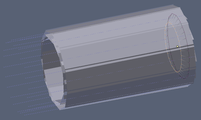
Next up, is the particle system. You can't use the blades themselves for the particle physics, because it will be far too slow. Instead, I used some very simple low poly replacements of each blade, stored on a seperate layer. That layer also includes the particle emitter (emitter and force field object should be on the same layer, otherwise they don't interact).
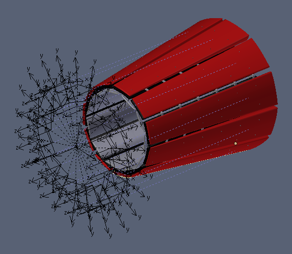
Particle emitter and force field objects.
As you can see, the particles are emitted outward a bit, to make sure they flow along the edge of the force field neatly. To make sure the particles are emitted outwardly in an even circle, make the particle emitter smooth, not solid.
You don't want the low ploy replacement blades to be rendered, so you have to make a material which makes them invisible. The force field and material settings are as follows:
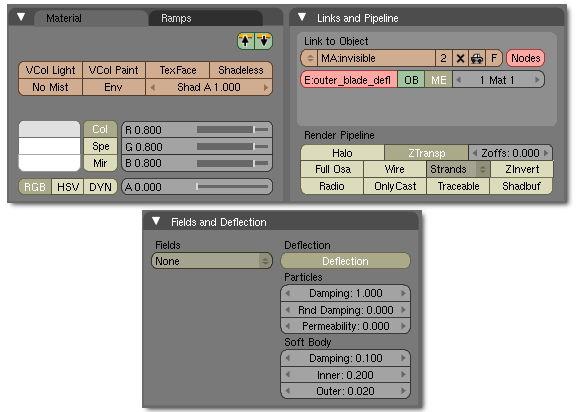
Force field and material settings for the low-poly replacement blades.
As for the material of the particles, the best way to see how I did that, is in the .blend files. It involves quite a few settings and material IPOs. If you want to change the color, you should do so in the IPO window, or by setting a material key on frame 1 and 100 for start and end color. You can also import the material and use it as-is (the material is called "exhaust").
4. Epilogue
I'll leave it up to you to add some materials and additional modelling. You can also use the example engine as-is (provided you don't violate the creative commons license, mentioned at the bottom of this page).
As you may have noticed, the amount of particles used is extremely high (100.000, which is the maximum), and the duration of the particle effect isn't very long. Extending the length of the particle effect causes the particle density to be too low. Perhaps some tweaking is possible, so that less particles are required, but I would really welcome a new feature in blender: the ability to set an amount of particles emitted per frame. The current "total amount / duration" fiddling is kind of annoying...
A good tip before you start assigning constraints, is to have all the objects parented to a main control empty (for moving the engine around) first. (well, except for objects that should not be parented to it directly, such as the constraint target empties). I didn't do that, and as a result, my constraints are messed up when I parent all the objects to a main control empty. If anyone knows a way to do that without having to recreate all the constraints, I'm all ears.