Relay and MOSFET speaker protection
Co-authored by Wolfgang Trinks.
1. Introduction
An important feature of an audio amplifier is to provide a system to protect your speakers in case the amplifier breaks down and puts DC on the speaker terminals. No speaker will take kindly to the presence of 50V on its voice coil, so that has to be prevented. One way of doing that is to include a VI limiter in the amplifier or power supply. However, it's hard to design one that doesn't negativly influence the sound quality when the amplifier is driven near its maximum (which happens sooner than you might think). Other solutions include polyswitches, fuses, etc. But a good and pratical solution is a relay with DC sensor.
However, you need to pay attention to how you wire and use your relay and how to protect against arcing between the contacts. Breaking 50V at 12A is quite a hard thing to do, but also repeated breaking of lower currents has its effects. But as the following experiments will show, there are ways to do it.
As the article will show, having relays in the speaker signal is not perfect. If you feel confident enough, and especially dealing with high power amplifiers, you may want to opt for a crowbar solution. McIntosh has done this in their high power designs. It works similarly to a speaker relay, but the relay (or MOSFET/triac/etc) is located over the output of the amplifier. On a fault, it will short-circuit the output, subsequently blowing the power rail fuses. This saves all problems with having a relay in the speaker path, but of course, you also don't get any start-up and shut-down muting and the device needs to be serviced after a protection event.
UPDATE: the times have cought up a bit and nowadays solid state relays are viable. There are MOSFETs with very little Rds(on) and isolated driver chips that operate the gate with a fast, stabilized signal, reducing switching losses in the MOSFET. Will they hold up to scrutiny?
I made videos of the experiments so that you can see what happened, and even revisit the subject in a full video at the end.
2. Test circuit
I designed and built the following test circuit:
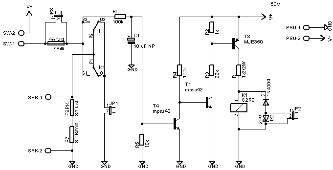
DC circuit tester schematic.
The detector circuit is copied from Rod Elliott's P33. It's a simple first-order filter driving a normally-on transistor switch.
The 4A fuse is what the rail fuse in an amplifier would be. When not using an actual speaker, the 3.9R resistor and 3A fuse are a simulated speaker. The fuse will tell me if the speaker has received too much punishment.
Its power supply is a 2x18V 8.33A, recitified to 50V. Supply capacitance is 20.000 µF.
3. Relays
I tested two relays for these experiments. The Amplimo LRZ and the Omron G2R-1-E.
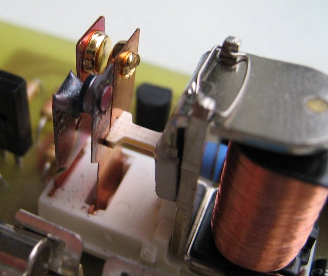
The Amplimo LRZ is a special relay designed specifically for speakers. It has two contact areas, one of tungsten (to take the arc upon making and breaking contact) and a gold one to bypass the tungsten contact (tungsten has a very high melting point, but it is a poor conductor). It looks like this on the inside:
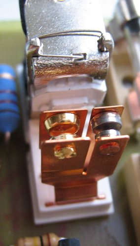
Amplimo LRZ relay.
The Omron G2R-1-E is a normal single pole dual throw relay:
Omron G2R-1-E relay.
4. Experiments
I wanted to test the following aspects:
- Does a snubber circuit help to quench an arc? In my tests I used a 100 Ohm resistor + 1 µF capacitor, connected over the relay contacts.
- What happens when you do and don't connect the speaker to ground in fault-mode.
- The effects with a simulated speaker (3.9 Ohm resistor and 3A fast fuse) and a real 8 Ohm driver.
The amplimo is a single throw relay, so point 2 doesn't apply to that.
I planned the following experiments:
- Test 1.1: Amplimo LRZ, with snubber, simulated speaker.
- Test 1.2: Amplimo LRZ, with snubber, real speaker.
- Test 1.3: Amplimo LRZ, no snubber, simulated speaker.
- Test 1.4: Amplimo LRZ, no snubber, real speaker.
- Test 2.1: Omron G2R-1-E, with snubber, NC contact to ground, simulated speaker.
- Test 2.2: Omron G2R-1-E, no snubber, NC contact to ground, simulated speaker.
- Test 2.3: Omron G2R-1-E, with snubber, NC contact not to ground, simulated speaker.
- Test 2.4: Omron G2R-1-E, no snubber, NC contact not to ground, simulated speaker.
- Test 2.5: Omron G2R-1-E, with snubber, NC contact not to ground, real speaker.
- Test 2.6: Omron G2R-1-E, no snubber, NC contact not to ground, real speaker.
5. Results
5.1. Amplimo LRZ
The relay, simulated and real speaker all held up fine in all tests. I performed the test dozens of times and there was no arcing. The speaker made a pop but survived, and the simulated speaker's 3A fuse remained intact (although you could see the filament deform).
Also interesting is the scope capture of this relay. I made two, one with the zener in the back-EMF suppression circuit and one without (by placing a jumper on JP2).
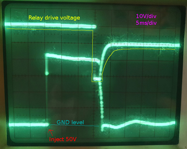
Amplimo LRZ scope capture with back-EMF zener D2 in-circuit
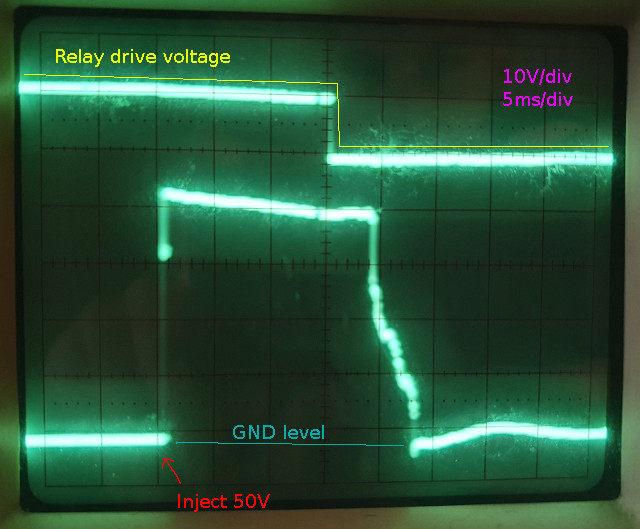
Amplimo LRZ scope capture with back-EMF zener D2 bypassed
Even though the relay faired well, I performed some preliminary experiments with the LRZ before and at some point, an arc did strike and the relay was destroyed:
Amplimo LRZ melted.
The simulated speaker also didn't survive this (the 3A fuse blew). It was an unfortunate accident that I was not able to reproduce.
5.2. Omron G2R-1-E
This relay faired a little less well, even though it's quite a sturdy one (16A at 30Vdc).
I'll start with the experiments where the NC contact was not connected to ground. Even with a snubber circuit, and arc formed. With the simulated speaker, the 3A fuse blew after the arc was sustained for about a second. With a real speaker, it was even worse. The arc was sustained for about five seconds while the speaker was at maximum excursion, reproducing the sounds the plasma arc made. Obviously, the speaker didn't like this... The funny thing is, though, that it survived the abuse. However, it should be clear that you don't want to tempt fate and test if you precious drivers will survive that too.
I didn't even do the experiments without snubber, because if with snubber the relay arcs, it would do so without one too (I confirmed this in preliminary tests).
Here are videos of the experiment:
Then the experiments where the NC contact was connected to ground. It behaved pretty well. An arc formed, but because the arc is to ground now, as opposed through the 8 Ohm speaker, the current exceeds the 4A rail fuse by a lot, so that blew. The arc was momentary and both simulated and real speaker survived. Even the relay was relatively intact. It showed some charring, but not much.
Here is the video of the experiment:
6. MOSFET relays
Since this article was originally written, improvements have been made in the area of solid state / MOSFET relays. With a couple of high-end MOSFETs and an isolated driver like the Si8751 or Si8752, you can make a good solid state relay. A reader contacted me about this and sent me his design to test. It's based on the aforementioned driver chip, and IPB038N12N3 MOSFETs. These MOSFETs have a very low Rds(on) of 3.8 mOhm and a high reverse avalanche rating.
As a first test, I wanted to compare the cut-off behavior. Earlier, we have the cut-off behavior of the Amplimo LRZ, which we can use as a reference. This is the MOSFET's behavior:
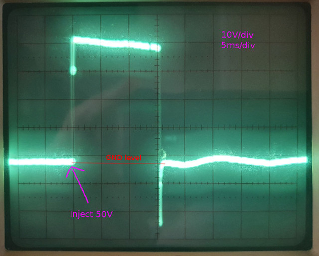
Capture of cut-off of 50V into single driver.
We can see the cut-off time is exactly the same as the relay drive signal (15 ms). We also see back-EMF. The MOSFET needs to have a high enough avalanche rating to deal with that, or you have to provide other means of protection. We'll explore this later, in a video.
To get a sense of how it operates in the real world, here's a video of repeated cut-off:
Another thing we want to know, is how well it can handle abuse. You'd think short-circuiting an amplifier using a relay like this shouldn't matter, because these MOSFETs can handle 120A. However, as its supply voltage will drop, will it still function properly? See the in-depth analysis video below for details.
7. Relay reliability
Relays wear down due to contact arcing. As an example, the Parasound HCA-1500 uses an Omron G4W relay:
- Specified maximum resistance: 30 mOhms
- Measured new: 2.8 mOhms at 1A (contact pair #1). 2.8 mOhms at 1A (contact pair #2)
- Failed relay from normal use, causing audible distortion: contact pair #1: 83 mOhms - cold. after 5 min at 1A: 141 mOhms. Failed at 5A inreversibly. Contact pair #2: 62 mOhms - cold, after 5 min at 1A: 85 mOhms
Apparently relays can cause audible distortion, which was the reason this amp was serviced. This topic requires further investigation and warrants a separate article.
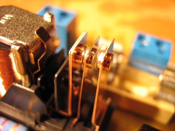
Also have a look at this relay from a Sansui 9090, which was never used to cut fault current (just normal operation):
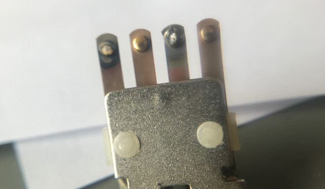
Worn relay from a Sansui 9090
Avoiding this kind of wear on a relay can be done, but it takes some effort. For starters, the mute circuit of the amplifier should include some kind of detection of loss of (mains AC) power to avoid the amplifier turning off power during turn-off noises. However, this does not protect against users turning off the amplifier mid-signal. A 100% robust setup mutes the input to the power amplifier (section) a short while before turning off the relays. However, this solution seems rarely used.
8. A second look
Nine years have progressed since the original article. Let's take a second look, looking at wiring and driving techniques, contact arcing, MOSFET avalanche rating, MOSFET reliability, short circuits and unexpected side issues.
And even more short-circuit tests:
You can also watch that on Youtube.
9. Conclusion
One very important conclusion can be drawn from this: wire the relay so that the speaker is connected to ground through its NC contact. Even if your relay is underrated, you can get good protection that way. In my tests the contacts didn't even weld together, so the relay could be reused, but my advice is to consider the relay as expendable; when it's been used to break fault current, replace it with a new one when you repair the amplifier. The Omron G2R-1-E has a transparent cover (which I removed for clarity) which is very convenient in this case, because you can see you need to replace it.
Also, you can't asume that any commercial DC protection system is wired up correctly. I know for a fact that the Velleman K4700 does not have the speaker wired to ground with the NC contact, so that circuit is unlikely to protect your speakers. The relays are even lighter than the one I tested, so if you use one of those, you might want to rewire it (which is difficult, because the speaker is not connected to the moving contact, the amplifier is. You'd have to remove the relay from the board).
What could also be imporant, is that your amplifier has fuses per channel, as opposed to for the entire amp. When an arc strikes, it's the rail fuse's job to blow so that the arc is quenched. If one amplifier has a maximum current rating of 4A, two amplifiers would be 8A. An 8A fuse is a lot harder to break than 4A.
Also, if the detector doesn't have its own power supply (which it should) make sure you wire the detector so that it doesn't lose power when the rail fuse blows. It should be wired before the amplifier's fuses, with a fuse of its own. The reason is simple: it needs power to operate. If your amplifier has a negative fault, the relay will turn off, blowing the negative rail fuse. Your amplifier will most likely then have a postive fault (because negative supply has disappeared). Some DC detectors require the presence of both + and - rails to operate and in this scenario, it will no longer be able to detect the postive fault.
When using MOSFETs, using a separate power supply for the detector/protector is even more important. As shown in the video, faults, like short circuits, cause unpredictable behavior in the power supply and can cause MOSFETs to go into ohmic mode, which makes it far more likely to blow up because of thermal stress.
10. Downloads
- Video of repeated cut-off using MOSFET on test speaker driver.
- Video of test 2.1: Omron G2R-1-E with simulated speaker, NC to ground.
- Video of test 2.3: Omron G2R-1-E with simulated speaker, NC not to ground.
- Video of test 2.5: Omron G2R-1-E with real speaker, NC not to ground.