Bi-amping the Acoustic Energy 120 speakers
Introduction
As Rod Elliott explains eloquently, bi-amping is a highly benificial way to drive speakers. Although nothing new, real bi-amping is still not the default (or available at all) in home Hi-Fi audio. Even high-end speaker manufacturers insist on using passive cross-overs, and go out of their way to design an 'audiophile quality' one, and use that as a unique selling point. But even then, they don't make it high quality by using proper zobel impedance compensation and such, but by using very expensive coils and capacitors. But no matter how expensive an inductor or capacitor might be, you can't get around their deficiencies, because they are mathmatically defined.
Often you see an attempt at bi-amping, by removing the bi-wiring clamps from the backpanel and have two amplifiers drive the existing cross-over filter. Even speaker manufacturers refer to this as bi-amping, and even though it's true in the strictest sense of the word (because you use two amplifiers per speaker), it's not real bi-amping until you remove the passive crossover from the speakers and perform the filtering at line-level, preferably phase coherent (and preferably 24 dB/octave, or higher when feasible).
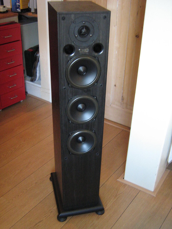
The Acoustic Energy 120 speakers are three-way and my goal was to replace the low-to-mid crossover filter with an active one. This article will describe the process, and allows you to repeat it with less damage to the interior :)
Step 1: Disassembling
The first thing I wanted to do, was to find out what the current cross-over frequencies were. To that end, I e-mailed Acoustic Energy technical support and they were kind enough to give me the manual. It stated:
High performance 2nd/3rd order at 375 Hz, 3.2 khz. Film capacitors with low distortion toroid inductor for bass. High resolution continuous crystal copper conductors to drive units.
I was pleased to read that, because it meant that my target frequency of 300 Hz was attainable. 300 Hz, on average, is the mid-point in the power distribution, so splitting it there means the most gain in effective power. Read Rod Elliott's article to find out more about that.
But, pig-headed as I am, I still wanted to reverse-engineer the existing cross-over filter. I needed to anyway, because I needed to know what components to by-pass to remove the filters in question. Unfortunately, this was not as easy as it sounds. The wires were too short to simply unscrew and take out the back panel, so I had to remove all the drive units first. And then, I found that the bolts were soldered in place. Understandable, but very annoying.
This is the cross-over as it was:
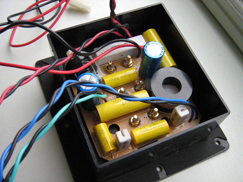
Cross-over circuit board, as it was originally.
One thing that stands out, is that even though the manual says it uses film capacitors, there are also bipolar electrolytics in there. Sonically not an issue, but because they have to handle high currents, they wear down quickly.
This is me desoldering the bots:
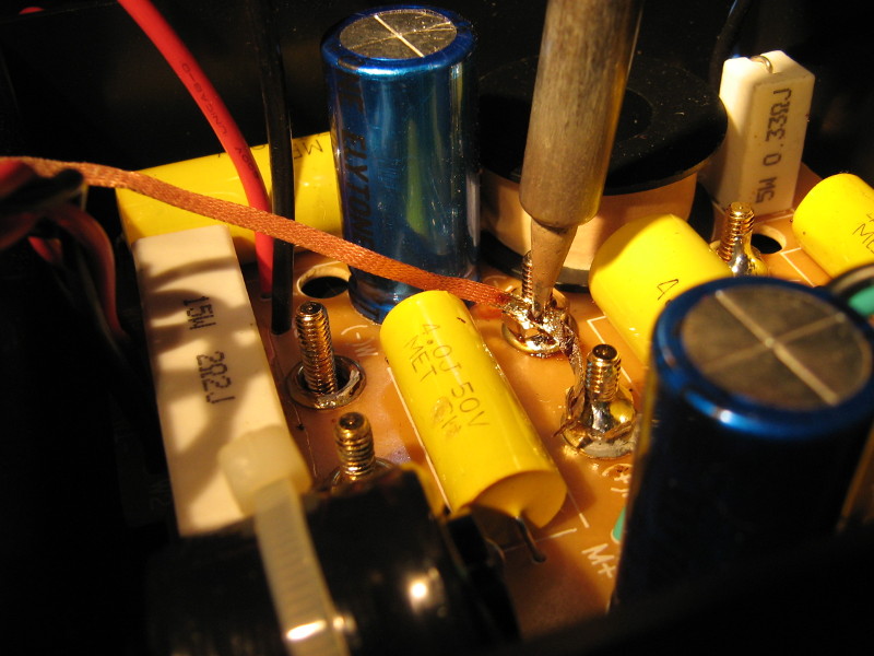
Desoldering the bolts on the cross-over.
As you can see, I used solder wick to get rid of the solder. It works, but it does get everything very hot. This caused some problems. First, you have to know that the bolts rest in non-round holes in the plastic (the one at the bottom is still somewhat intact):
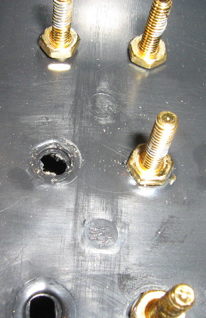
Banana plug mounting.
The heat softened the plastic, deforming the normally perfect-fitting holes.
The other problem was that one of the bolts broke when I was unscrewing the nut. My advice to you: wait till the bolt gets cold to unscrew, because hot metal is weaker. And, make sure all the solder is removed. Or actually, when you use the information I give you, you don't need to desolder anything.
Step 2: Reverse engineering
When I finally had the entire thing disassembled, I was able to make a schematic of the filters. Because it's tri-wirable, there are three separate filter stages. Most component values were printed on them. I only had to measure the midrange and tweeter inductor, and the inductance of the drivers.
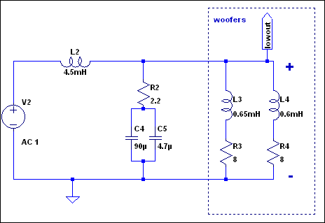
Woofer crossover.
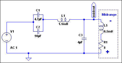
Midrange cross-over.
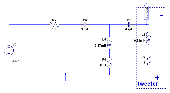
Tweeter cross-over.
One thing that stands out, is that the mid-range high-pass filter (C1 and C2) is a 1st order one, which contradicts what the manual states.
Simulating these schematics results in these plots:
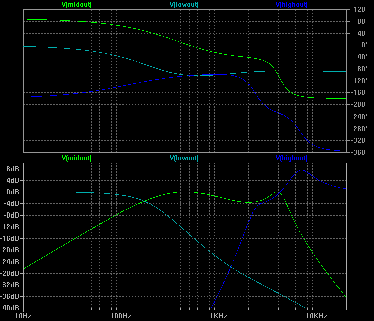
Cross-overs response.
Here is a simulation into a resistive load (no speaker inductance):
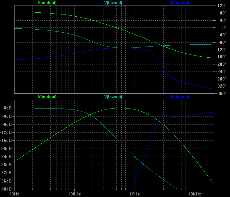
Cross-overs response, resistive load.
Wait. Low-to-mid cross-over point at about 175 Hz? How's that possible? Not only is it not the advertised 375 Hz, but it's also very low for a 3-way system. I contacted Acoustic Energy support about this, and they assumed my simulation was at fault. So, I connected the still unmodified speaker to my sound system and did measurements with REW:
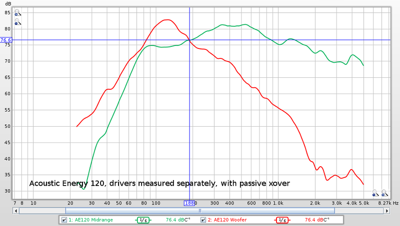
Passive cross-over SPL measurements.
These readings seem to confirm my simulation. Or, at least that the cross-over point is not near 375 Hz.
It seems that the actual design of the filter doesn't match the stated specifications. I e-mailed Acoustic Energy about it, hoping it will yield some answers. However, I didn't want to pester them, so I made it more of an FIY for them, giving them no obligation to reply. They probably have enough e-mail to deal with.
Bypassing the low-to-mid filter
To remove the low-to-mid filter, I had to make these modifications:
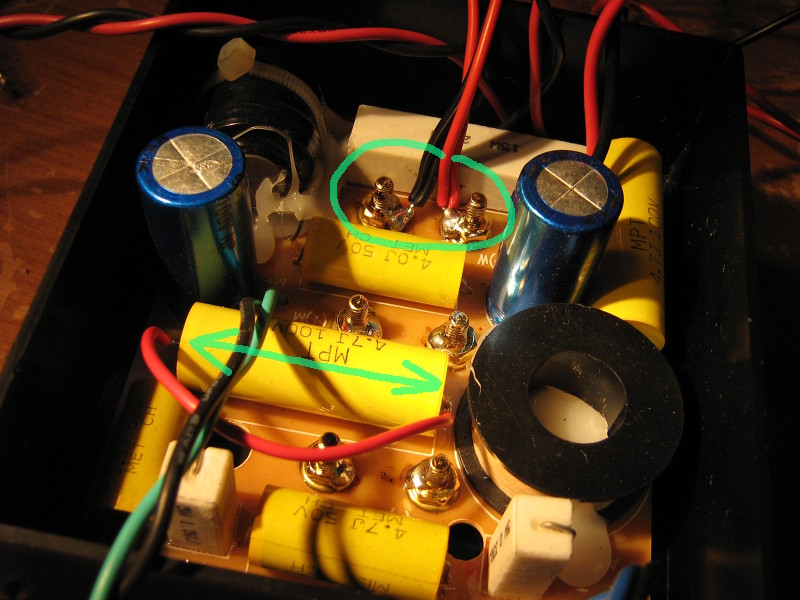
Low-to-mid cross-overs bypassed.
I did three things here:
- Bypass the marked film capacitor (which is C1 in the above schematic), to bypass C1 and C2.
- Connect the woofers directly to the back terminal, also as indicated in the image. Polarity should be reversed.
- Disconnect the off-board toroid inductor, L2 in the above schematic.
All steps are important, including the last one. If you don't disconnect it, you will get (potentially destructive) resonance between L2 and C4+C5. Luckily, it's very easy, because it can be easily unplugged, since it's mounted off-board.
As mentioned, the polarity of the woofers should be reversed. In the schematics above, you can see that the midrange and tweeter are wired out of phase, and the woofer is in phase. With active bi-amping, such reversals are not necessary, and we need to bring everything in phase. So:
- Wire woofers out of phase, so that all drivers are phase-reversed.
- Switch around the black/red screw terminals at the back. The thumb-screws are the only thing that have the black/red color, so you can easily unscrew and switch them, to have all drivers back in phase and the connections properly colored.
Cross-over frequency selection
Next step is choosing the new cross-over frequency. There are several considerations, as Rod Elliott outlines. His ideal frequency would be 300 Hz, but as he states, this is a hard task for most drivers. If I keep to the specs I obtained through reverse engineering, 300 Hz much higher the original construction. However, 175 Hz is such a low frequency for low-to-mid cross-over, that I really don't think it was meant to be crossed-over there.
I determined that both woofers and the midrange have their resonance at 90 Hz. Since you want to be about two octaves away from resonance (to avoid coloration of the sound), one would pick 360 Hz. Perhaps the 375 Hz the manual states was actually arrived at by this very same rule of thumb. It would make sense. But since my active filter will be 24 dB/octave (4th order), I think I can get away with picking 300 Hz, and staying outside what Rod Elliott calls the "intelligence band".
Calibration
Initially, I had both ends of the filter at equal gain, because there was no padding in the passive filter. However, I realized that by increasing the cross-over frequency to 300 Hz, the range between 175 Hz and 300 Hz was now produced by two drivers, as opposed to one. So, I took some REW measurements to determine the proper filter calibration.
This graph shows the acoustic output when both filters are at 0 dB gain (green) and when the low-pass is at -3 dB (approximatly) (blue):
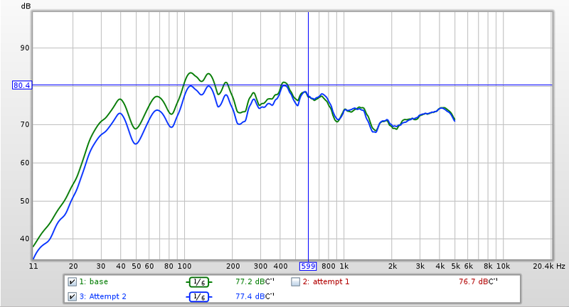
Low-pass filter adjustment.
This removed some bonkiness to the bass, because there was too much upper bass.
Listening
As mentioned in the chapter 'calibration', there initially was some bonkiness to the bass, which was disappointing. I don't really remember if this was the case with the passive filter, but whether or not that was the case, after recalibrating the low-pass filter, tonal balance was excellent.
The bi-amping improved matters greatly. Vocal clarity and imaging mostly, and I didn't even expect imaging to be improved. As they were with the passive filters in place, my main problems with the speakers were that male voices were too muffled, like standing outside a closed car that has it's radio on, and I could just not get the imaging right. Now, with bi-amping, imaging is unnervingly real, and so are voices, male and female.
The speakers on their own are somewhat weak in the bass, despite the claimed -3 dB frequency of 38 Hz. It might be this room. But, since it's joined by my ELF subwoofer, it really is no problem. I prefer the bass of my subwoofer, anyway.
I'm very happy with the result, and I'm glad I can add it to my existing sound system.
References
- Benefits of Bi-Amping (Not Quite Magic, But Close)
- Benefits of Bi-Amping (Not Quite Magic, But Close) - Crossover Frequency Selection
- My ELF subwoofer